Filtergram Wear particle Analysis is a Pro-active Predictive Maintenance System.
Wear Metals Particles are extracted from an oil sample then magnified up to a 1000X for wear mode identification.
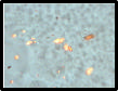
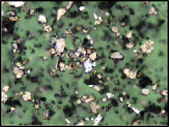
A Filtergram from the T56 in a VX SS @ 2000 klms from new.
Same Gearbox @ 20,000 klms on Mainlube 151 Synthetic E P Gear Oil
Same Gearbox @ 52,000 klms on Mainlube 154 Solid Boundary Synthetic E P Gear Oil
Cosmo VYSS T56 @ 30,000 klms on ATF
Cosmo VYSS T56 @ 33,000 klms on Mainlube 154 Synthetic Solid Boundary E P Gear Oil
Tiger SS T56 @ 30,000 klms on Transmax Z
Drewbites T56 @ 30,000 klms on ATF
Drewbites Diff @ 3,000 klms on Castrol LSD Oil
Ronny T56 @ 20,000 klms on Transmax Z
JD Biddle T56 @ 70,000 klms on ATF

Wear mode identification is possible when viewing
Pro-Active Maintenance uses the Wear Mode information to correct and prevent future reocurrence.
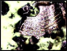
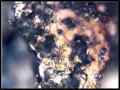
When the machine’s normal operation lightly defoliates the wear surface.
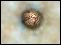
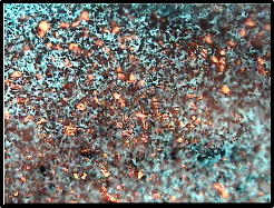
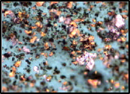
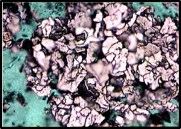
Normal Rubbing Wear Particles depending on the machine, are 0-10 microns sized platelets. In a gearbox situation Normal Rubbing Wear could register 0-60 ppm of wear metals using Atomic Absorption Spectrometer. This is a visual example of Normal Rubbing Wear Particles.
@ 600X Sized 5-10 microns.
These images are from machines that appear to be in an “exaggerated” Normal Rubbing Wear Mode.
If the wear mode is building, then it’s not normal. (Scuffing Wear)
They are the end result of other larger wear modes being milled down as they are forced through the load zone by the lubricant flow. They appear, as a heavy concentration of Normal Rubbing Wear Particles.

is the cause of most damage.
Below shows the normal “Lubricating Film Thickness” in each application in operating conditions. Particles larger than the “lubrication film thickness” become Three Body Contact Contaminate Particles as the lubricant flow forces them through the load zone, easily penetrating the lubricating film, continually damaging load bearing surfaces
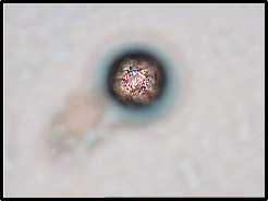
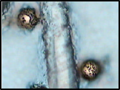
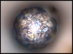
3 body Fatigue, Spheres, Laminar, Dark Metallo and Black Oxide Wear Metal Particles are made possible by Fluid Contamination.
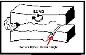
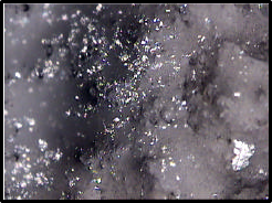
Spherical Particles sized 4-5 microns are generated in 2 and 3 Body Fatigue cracks on rolling bearing wear surfaces.
As the lubricant flow forces wear metals through rolling bearing tracks, 2 and 3 Body Fatigue cracks trap the wear metal debris, the rotation rolls the debris over and, building the Sphere until it is large enough to escape. Research has shown, as the bearing is failing, one to two million spheres will be released, pre-warning an up and coming bearing failure. Other Spheres are generated in gears, these Spheres are usually 10 microns or larger. The images below show Spherical Wear Metal Particles from gears and bearings.
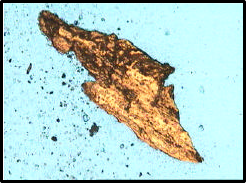
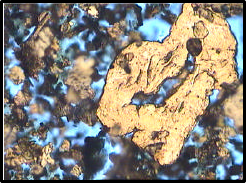
Sliding Wear occurs when the lubricants film strength has been insufficient in providing separation between two wear surfaces, allowing metal to metal contact. It’s like the glacier sliding down the hill, it bulldozers along the surface tearing everything off in it’s path. Severe sliding wear generates extreme heat, in some cases over 1000°C in the load zone. How many times you have seen
a large gearbox showing gear case temperatures above 100°C?
How much energy would it take to heat the gearbox to this temperature? How much energy is being wasted by tearing off metal, which could be turned into production?
To generate this heat, the machine is tearing off of 50 to 200 micron chunks of metal and releasing them into the lubricant flow. This forces the metal chunks through the rolling elements of the machine causing secondary wear. Gear faces subject to high temperatures over time, anneal the gear tooth surfaces, softening them promoting further wear.
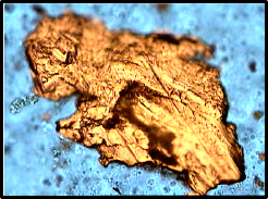
Here are examples of Sliding Wear Particles 500X-600X Sized 40-200 Microns.
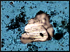


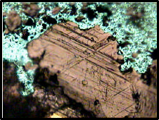
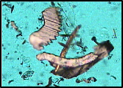
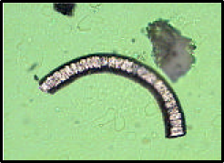
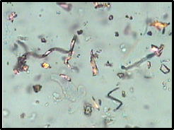
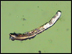
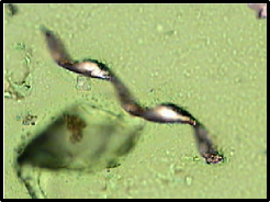
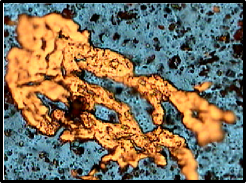
Cutting Wear Particles are caused by hard contamination, usually Silica (Sand), or other hard contaminants, or an acute angle of metal to metal contact that has occurred between the machine’s components.
The distinctive curled swarf, shapes of Cutting Wear Particles, show a hard contaminate has penetrated the lubricating film, gouging out the metal. Cutting Wear is an abnormal wear mode. Cutting Wear Particles results in machinery damage and should corrected as soon as possible.
Filtergram Analysis identifies all wear mode types present, then recommends changes and monitors the immediate effect of the changes to ensure success.
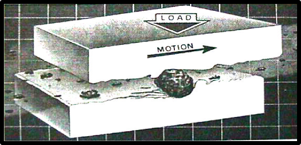
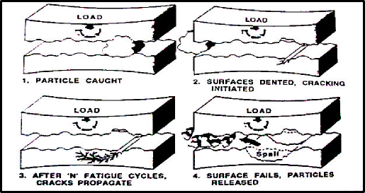
2 Body Fatigue Wear chunks occur when the machines cyclic application of the stress, is in excess of the design value.
The machine has been overloaded, past the capabilities of the metals surface, slightly collapsing the metals sub-surface creating a crack or dent.
Repetitive bruising in this area further fractures the metals sub-surface causing the area to eventually spall out. This creates the familiar deep pitting and scaring damage observed on load bearing surfaces. Spheres are usually generated in these areas.
Body Fatigue Wear Particles are flat platelets with a major dimension to thickness ratio of approximately 10:1, a smooth surface and a random irregularly shaped circumference.
These spalling metal particles are carried by the oil flow through other load zones, snowballing the effect and further damaging load-bearing surfaces.
Damage will continue to this machine until the contamination is completely removed
Filtergram Analysis identifies all wear mode types present, then recommends changes and monitors the immediate effect of the changes to ensure success.

Body Fatigue Wear Chunks are wear metal Particles that began when a foreign body was forced through the load zone creating a micro crack or dent. Repetitive bruising in this area fractures the metals surface, causing the area to eventually spall out. This creates the familiar loss of hardened surface, scaring and light pitting damage observed on load bearing surfaces.
These spalling metal particles are carried by the oil flow through other load zones, snowballing the effect and further damaging load-bearing surfaces.
Damage will continue to this machine until the contamination is completely removed.
Filtergram Analysis identifies all wear mode types present, then recommends changes and monitors the immediate effect of the changes to ensure success. If not corrected this wear mode will escalate in Scuffing Wear and eventual failure. Three Body Wear
Scuffing Wear
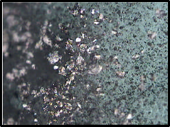
Scuffing Wear Typical of “Running In” mode.
New machinery must be “run in” to allow load-carrying surfaces to “bed in”. When the components of a machine are new, especially after an overhaul, bearings and gears can be sourced from may different places. There are hills and valleys present that must be smoothed out to achieve the correct “light defoliation” of the wear surface to settle the machine down into Normal Rubbing Wear mode.
After a machine has “bedded in” the machine must be flushed and refilled with fresh lubricant. If left, scuffing wear will be carried by the oil flow through other load zones, snowballing the effect generating 3 Body Fatigue Wear, then on to Laminar Wear and further damaging the new load bearing surfaces.
Damage will continue to this machine until the contamination is completely removed.
Filtergram Analysis identifies all wear mode types present then recommends changes and monitors the immediate effect of the changes to ensure success.
The images below are from a large reduction box that has been freshly overhauled and run for 100 hours and benchmarked.
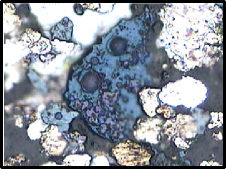
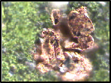
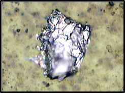
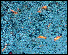
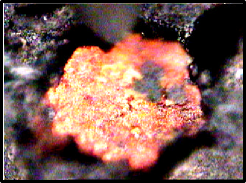
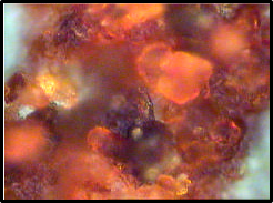
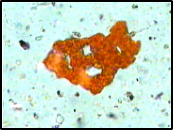
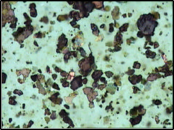
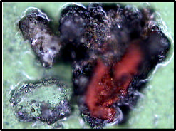
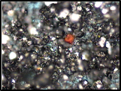
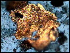
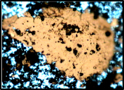
Red Iron Oxide Particles are easily formed when water is present in the system, or has been in the system in the past.
If heavy amounts of large Red Iron Oxide Particles are found in the sample, this will indicate the presents of water in the system.
Red Iron Oxide particles vary in colour and size with the amount of water present. The presence of other minerals, in the water and the size of the crystals, all have an effect on the way the Red Oxide Particles form. Below are several different forms of Red Iron Oxide Particles, the effect of the formation of these particles on the metal surfaces causes severe surface corrosion damage and subsequent loss of load carrying surface area, this is catalysed by the formation of the Red Iron Oxide Particles.
Filtergram Analysis identifies all wear mode types present then recommends changes and monitors the immediate effect of the changes to ensure success.
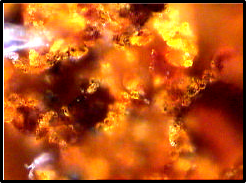
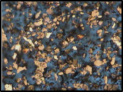
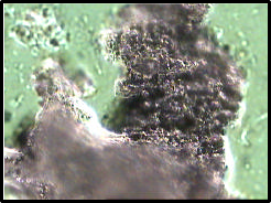
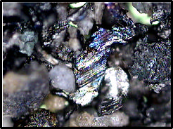
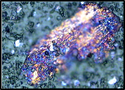
Dark Metallo & Black Oxide Particles are formed when machine is being over driven beyond the capability of the lubricant. The heat and pressure generated causes lubricant starvation. When Red Iron Oxide (rust), is forced through the load zone it polymerises and forms Dark Metallo-Oxide and Black Oxide Particles. Water is not present when Black Oxide Particles and Dark Metallo- Oxides are formed. There are many forms of Iron Oxides FeO, Fe2O3 and Fe3O4.
To rectify this wear mode the lubricant should be up graded to a product more suitable to the machines operating environment. It is not unusual to see particles oxidised to varying degrees of colour , from straw through to blue purple. Filtergram Analysis identifies all wear mode types present then recommends changes and monitors the immediate effect of the changes to ensure success.
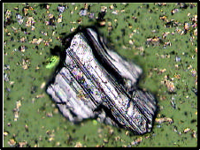
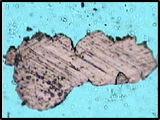
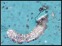
Laminar Wear is a secondary wear mode, which is the end result of all wear modes being forced through the load zone by the lubricant flow. Their passage damages load bearing surfaces, forming large “rolled out” particles that contain all wear modes created earlier. The machine’s rolling elements roll the abnormal Wear Metal Particles flat, to the distinctive length to thickness 30:1 ratio.
Typical operating lubrication film clearance in Industrial Ball Bearing, Roller Bearing and Meshing Gear Sets are of 0.1 to 1-Micron clearance. When spalls or breakages occur, or foreign contaminates are introduced to the lubrication system, the foreign particles could be 100’s of microns in size, the human hair is 60 to 100 microns in diameter. The lubricant flow forces these huge foreign particles, through the machine’s rolling gears and bearings causing extensive damage to the machines running surfaces.
As these chunks of metal, up to 500 microns in size, are forced through the bearings and gears, with a maximum clearance of 1 micron, they crush and mill down forming the 0 to 15 microns sized abnormal wear metals that register when an Atomic Absorption Spectrometer test is preformed. Most people have trended the wear rate using the Atomic Absorption Spectrometer from the local Caterpillar Agent or Fuel Company. The problem with this type of analysis is wear particles are required to be milled down by the machine’s rolling elements to the small size of 0-10 microns before they register in the test. Particles bigger than 10-micron increase the particle count but cannot be identified. This means this the Atomic Absorption Spectrometer often only registers the introduction of a contaminant 2 to 3 months after the event. Undetected contaminates cause extensive damage to the machine’s wear surfaces, shortening their life by cracking and denting the surface in the end forming other abnormal wear metals shown ahead. Filtergram Analysis identifies all wear mode types present, then recommends changes and monitors the immediate effect of the changes to ensure success.
Damage will continue to the machine until the contamination is completely removed.
Here are examples of Laminar Wear Particles 500X-600X Sized 40-200 Microns.
ISO SOLID CONTAMINANT CODE ISO 4406
|
Range Number 24 |
indicates |
80,000 to 160,000 |
particles per ml of oil |
|
Range Number 23 |
indicates |
40,000 to 80,000 |
particles per ml of oil |
|
Range Number 22 |
indicates |
20,000 to 40,000 |
particles per ml of oil |
|
Range Number 21 |
indicates |
10,000 to 20,000 |
particles per ml of oil |
|
Range Number 20 |
indicates |
5,000 to 10,000 |
particles per ml of oil |
|
Range Number 19 |
indicates |
2,500 to 5,000 |
particles per ml of oil |
|
Range Number 18 |
indicates |
1,300 to 2,500 |
particles per ml of oil |
|
Range Number 17 |
indicates |
640 to1,300 |
particles per ml of oil |
|
Range Number 16 |
indicates |
320 to 640 |
particles per ml of oil |
|
Range Number 15 |
indicates |
160 to 320 |
particles per ml of oil |
|
Range Number 14 |
indicates |
80 to 160 |
particles per ml of oil |
|
Range Number 13 |
indicates |
40 to 80 |
particles per ml of oil |
|
Range Number 12 |
indicates |
20 to 40 |
particles per ml of oil |
|
Range Number 11 |
indicates |
10 to 20 |
particles per ml of oil |
|
Range Number 10 |
indicates |
5 to 10 |
particles per ml of oil |
|
Range Number 9 |
indicates |
2.5 to 5 |
particles per ml of oil |
|
Range Number 8 |
indicates |
1.3 to 2.5 |
particles per ml of oil |
|
Range Number 7 |
indicates |
0.64 to 1.3 |
particles per ml of oil |
|
Range Number 6 |
indicates |
0.32 to 0.64 |
particles per ml of oil |
|
Range Number 5 |
indicates |
0.16 to 0.32 |
particles per ml of oil |
|
Range Number 4 |
indicates |
0.08 to 0.16 |
particles per ml of oil |
|
Range Number 3 |
indicates |
0.04 to 0.08 |
particles per ml of oil |
|
Range Number 2 |
indicates |
0.02 to 0.04 |
particles per ml of oil |
|
Range Number 1 |
indicates |
0.01 to 0.02 |
particles per ml of oil |
![]()
The ISO Solid Contaminant Code ISO 4406 is the single most wide spread system for representing contaminant levels in Hydraulic or Lube Oil Systems.
The first range number is separated for the second range number by a slash, (eg 15/12) From the chart, the particle count ranges correspond to each adjacent range.
A typical ISO Code for a hydraulic system is ISO 16/13. By checking the Range Chart we can see that
Range Number 16 means there are between 320 and 640 particles per ml of oil bigger than 5 microns.
And
Range Number 13 means there are between 40 and 80 particles per ml of oil bigger than 15 microns included in this first total of between 320 and 640 particles per ml of oil.
This equates to approximately I milligram of dirt per litre of fluid or 1 ppm.
A Vickers Chart of Recommended Cleanliness Codes uses the Pal or Vickers System, same as this ISO 4406 System’s Range Numbers. Vickers being a leading Hydraulic Equipment Manufacturer developed this system to prevent unnecessary wear in hydraulic systems.
The difference between the Vickers System and ISO 4406 is that Vickers also consider particles 2 microns and greater, this range is recorded by adding another set of numbers in front for the number of particles greater than 2 microns. eg 18/15/12, or;
(1300 to 2500 particles >2 microns/ 160 to 320 particles >5 microns/ 20 to 40 particles >15 microns).
At all times the first Range Number will indicate the total number of particles of all sizes per ml of lubricant, the subsequent Range Numbers indicate the sizing of the particles in this first total
Both systems without the previous page’s chart offer limited information until the system has been learnt and understood. Once this is accomplished the user will notice any unusual Range Number changes and be very accurate with early detection and correction of abnormal wear modes.
